MRI-compatible Actuator for Artificial Tactile Stimulation
Working with Dr. Netta Gurari in the Robotics and Sensorimotor Control Lab, our goal is to create and trace a sensory percept through the brain using an artificial stimulus and fMRI.
 Demonstration video
Abstract
The purpose of this device is to deliver a tactile stimulus at an individual’s fingertip in a controlled manner in an MRI environment. The greater aim of this work is to use the apparatus to assess deficits in tactile perception, and where those deficits present themselves along the DCML pathway, up to and through the brain.
Somatosensory Overview
Once a sensation is perceived, sensory information travels via Dorsal Column-Medial Lemniscal pathway, or via the anterolateral column (noxious/thermal)[2]. After traveling up the spinal column and reaching the medulla, the sensory information decussates, continuing up through the thalamus, and terminating at the somatosensory cortex.
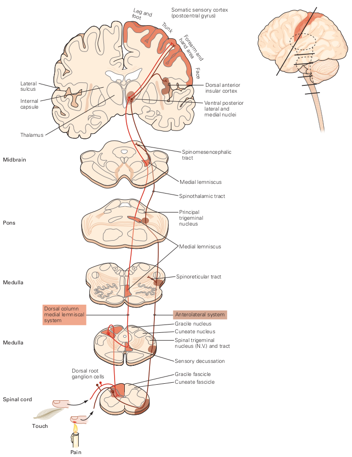
Figure 1: The dorsal column-medial lemniscus (DCML) pathway sends sensory and proprioceptive information. Above, lines indicate position of slices presented. Source: Kandel, Neural Science, 5th ed.
Touch Sensory Perception
The dermis contains four mechanoreceptors, each with their own specialization[1]: Meissner Corpuscles for surface textures, Ruffini Corpuscles that react to skin stretch, and Pacinian Corpuscles are sensitive to vibrations and tool use.
Merkel cells are sensitive to deep, static touches, and low vibrations (0-100Hz). They have a small receptive field and transduce detailed information about the surface they’re interacting with. Merkel cells signal the static aspect of a touch stimulus, such as pressure, whereas the terminal portions of the Merkel afferents in these complexes transduce the dynamic aspects of stimuli.[1]
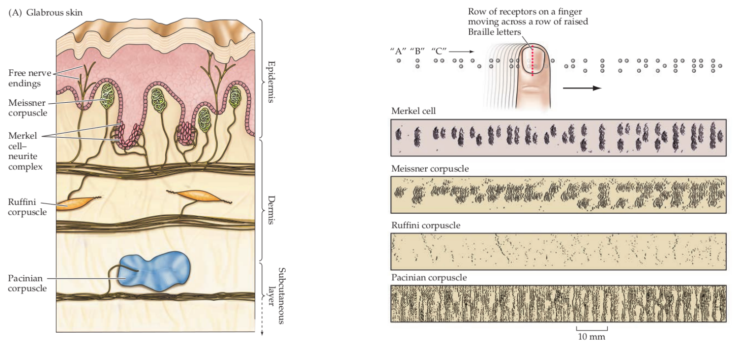
Figure 2: Receptors in the fingertip and the information they transduce Source: Purves, Neuroscience, 6th ed.
Stroke Overview
Strokes are caused by a disruption of blood flow to the brain, either by a clot in the blood vessel (ischemic stroke) or by a rupture (hemorrhagic stroke). Without oxygen or nutrients supplied by the blood stream cells begin to die. The scope of the damage is in part determined by the arterial network; neighboring branches of blood vessels may still be able to serve the affected area, limiting the potential damage. The same sort of stroke event can produce different effects between individuals.
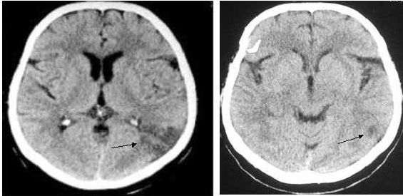
Figure 3: CT scan of individual who expereinced stuttering as the result of a stroke in the left parietal lobe. Source: Sahin et al. 2005
Apparatus
Pneumatic Actuator
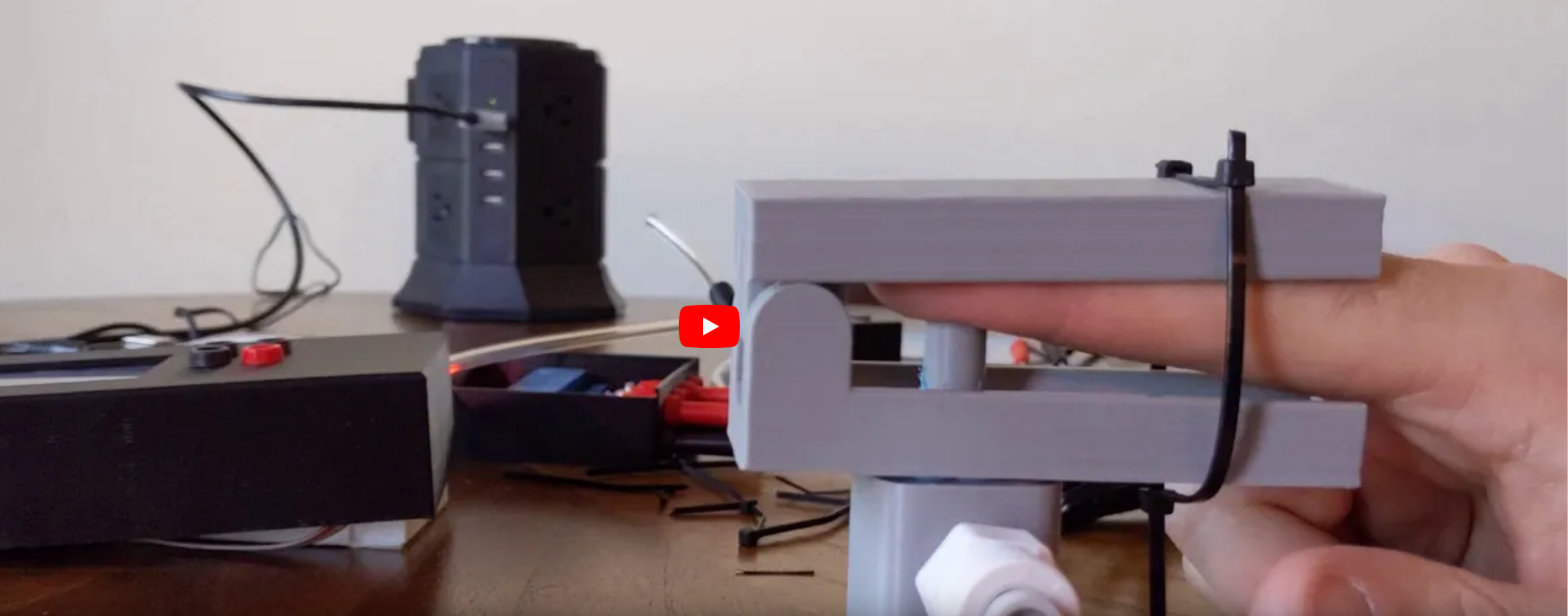
To create the sensory signal I developed a small pneumatic piston that presses on the finger. Pneumatic systems use air as a working fluid. The piston is 3D printed using PLA polymer and is attached to an air compressor for pneumatic action. System is controlled using a PIC32 microcontroller and communicates serially with a computer. Two varaints of the piston were developed: a pneumatic return and a spring return. More information about the design can be found here.
Figure 4: User demo of the pneumatic actuator
Control
Air is directed in and out of the piston using a solenoid controlled by the PIC. The solenoid has three (3) positions; allowing airflow to the cylinder, allowing airflow from the cylinder, and a neutral position that restricts all airflow.

Figure 5: Solenoid directing airflow. Graphic source: lunchboxsessions.com
From there air is passed to a pressure regulator controlled by the PIC. Adjusting the pressure changes the speed and force in which the piston actuates.
The PIC32 is a 32 bit, general purpose, microcontroller. It acts as the brains of the system, listening to the pressure sensors and directing the pressure regulator. It can also recognize when the probe has touched the fingertip. Real time system information is displayed on the screen and transmitted serially to a listening computer.
Figure 6: Actuating piston
Discussion & Future Work
During development I made it a priority that the device was MRI-compatible, which influenced many of the design considerations and challenges. The decision to use a pneumatic system made it so there is no interference from the apparatus during the MR imaging process. However, air is a compressible fluid which makes it difficult to control. A hydraulic system was considered to address that but was never implemented due to concerns about leakage.
That said, leakage still proved to be a nuisance throughout the project. Pistons of various sizes were printed in an effort to dial in the tolerances, but ultimately will require better surface finishing. In addition to O-Rings, piston rod rings were incorporated into the design to alleviate the issue. Though not unsuccessful, it was not utilized in the final design.
The control loop has two pressure sensors and one touch sensor. An optical linear encoder using fiber optic cables was considered, which would’ve provided more certain feedback of the piston, but ultimately was shelved due to time constraints.
Future work with this project will primarily focus on characterization of the actuator, as well as making each element more robust and providing the framework for which development can continue. The two largest lessons were in time management, setting realistic expectations and goals, and project management, learning how to juggle multiple facets of a project and navigating the way forward.
Knowing if/when the piston engages with the finger is also important. The controller currently takes advantage of the CTMU module on the PIC32. For it to work, the surface that the fingertip engages with must be conductive (and MRI-compatible, ie. aluminum foil) for it to work. Studies examining the heating effects of MRI scanning have shown that no significant heating occurs with nonferromagnetic materials.[2] This means the individual won’t risk burning their finger. And because the peripheral is non-moving, there’s no risk of interference during imaging[3].
More Information
More information and details specific to the project, please see my Github link here.
References
[1] Purves, D., Augustine, G., Fitzpatrick, D., Hall, W., LaMantia, A., Mooney, R., Platt, M. and White, L., 2018. Neuroscience. 6th ed.
[2] Kandel, E. R., 2013. Principles of Neural Science. 5th ed.
[3] Buchli R, Boesiger P, Meier D. Heating effects of metallic implants by MRI examinations. Magn Reson Med. 1988;7(3):255-261. doi:10.1002/mrm.1910070302
[4] Fischer GS, Krieger A, Iordachita I, Csoma C, Whitcomb LL, Gabor F. MRI compatibility of robot actuation techniques–a comparative study. Med Image Comput Comput Assist Interv. 2008;11(Pt 2):509-517. doi:10.1007/978-3-540-85990-1_61